INDIAN ARMED FORCES CHIEFS ON OUR RELENTLESS AND FOCUSED PUBLISHING EFFORTS
The insightful articles, inspiring narrations and analytical perspectives presented by the Editorial Team, establish an alluring connect with the reader. My compliments and best wishes to SP Guide Publications.
"Over the past 60 years, the growth of SP Guide Publications has mirrored the rising stature of Indian Navy. Its well-researched and informative magazines on Defence and Aerospace sector have served to shape an educated opinion of our military personnel, policy makers and the public alike. I wish SP's Publication team continued success, fair winds and following seas in all future endeavour!"

Since, its inception in 1964, SP Guide Publications has consistently demonstrated commitment to high-quality journalism in the aerospace and defence sectors, earning a well-deserved reputation as Asia's largest media house in this domain. I wish SP Guide Publications continued success in its pursuit of excellence.


- MoD initiates comprehensive review of Defence Acquisition Procedure 2020, pushes for defence reforms
- G7: The Swansong
- Kalinga Connect: South Asia to Polynesia
- Advanced MRSAM for India for a greater firepower
- Must Credit DRDO for Operation Sindoor, now what is next for defence R&D?
- Operation Sindoor | Day 2 DGMOs Briefing
- Operation Sindoor: Resolute yet Restrained
Hovercraft
Bid for Air Cushion Vehicles
ACV can patrol coastal regions to prevent incursions from drug and people traffickers. They are also likely to provide a far more stable platform compared to boats. Fifty years from now, with seawaters rising as a result of global warming, the commuter hovercraft would be more practical than the car, for getting to work.
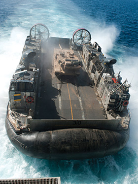
The Indian Navy has issued a request for information (RFI) for air cushion vessels (ACVs) for independent patrolling and surveillance of remote areas. The primary mission of ACVs will include independent patrolling and surveillance mission of remotely located islands; search and rescue missions; and limited capability for humanitarian aid and disaster relief missions.
How ACV Works
ACV ejects high-pressure air downwards, which provides an air cushion on which it travels over surfaces without touching it. The air cushion provides almost a friction free highway on a variety of surfaces like water, desert and plain areas. ACV use a skirt system, where the air from the lift fans is routed to a narrow slot around the edge of the hull and bounded by a skirt. The high pressure air is contained in a skirt which is placed around the vehicle. Distribution of this air from the fans to the periphery is through a large-volume plenum chamber or an annular jet system so as to enable even distribution of airflow, independent of the length of the direct path. A plenum chamber is a pressurised housing, containing air at a pressure higher than the surroundings. In a plenum chamber vehicle, the rate of leakage of this air from underneath the vehicle is reduced by placing a skirt around the lower edge of the craft. In an annular (circular) jet vehicle, the rate of leakage is reduced by directing the air downwards and inwards from the outer edges of the vehicle. Some of them have a specially designed wing that will lift them just off the surface over which they travel when they have reached a sufficient horizontal speed. ACV is also known as a ground-effect machine (GEM) or a Hovercraft. An ACV moves on a cushion of air, and manoeuvres over water and most terrains, from asphalt to quicksand. The air cushion also reduces or eliminates damage to ground surfaces. Thus an ACV is the ideal transport when environmental damage is of concern. It can also travel on tricky surfaces such as thin ice, swamps and marshes.
Early Years
Emmanuel Swedenborg, a Swedish designer and philosopher, designed the first ACV in 1716. The project did not fructify as it was much ahead of its time. In the mid-1870s, the British engineer Sir John Thornycroft built a number of model craft to test the effect of air-cushion. However, he was also ahead of its time as no technology existed then to translate the design into a working machine. However, a few US and European engineers continued work on the problems of designing a practical craft. In the 1950s, British inventor Christopher Cockerell started testing the concept of ACV and in 1955 he obtained a patent for a vehicle that was “neither an airplane, nor a boat, nor a wheeled land craft.” He also demonstrated the concept to the defence forces but was unable to inspire them. However, he perseveres and crossed the English Channel in 1959 in a single person Hovercraft. In 1962, a British ACV became the first to go into active service on a 31-km ferry run. The maximum size of ACVs can be over 100 tonnes with speed of 160 kmph. Small ACVs called flarecraft are extremely popular and can carry up to eight persons at 240 kmph.
System
To put it simply, place an ACV which has a hull, fans which provide the air, propellers for movement on the surface and a skirt to contain the air. The design of the skirt is very important and there are generally two basic types.
Skirts, Propellers, Propulsion and Directional Control
Rigid Sidewall ACV: The rigid sidewall ACV has fans powered by lift engines that create an air cushion under the vehicle which lifts it and also creates a sort of highway for the ACV to travel. The rigid side walls which surround the air chamber, brush the surface they are moving on or are immersed in it, to reduce the leakage of air. The air can also be used for propulsion but often separate means are used. The rigid sidewalls partly sail through the water and practically convert the vehicle into a catamaran. The hull of virtually all conventional ships and boats has a mono-hull configuration which is more stable but adds to the drag. On the other hand catamaran is a type of multi-hulled boat or ship consisting of two hulls, joined by a structure which reduces the drag. The wide beam and the catamaran hull are extremely stable even in high seas. The air cushion is then sealed by flexible rubberised skirts at the bow and stern. Such an arrangement allows the ACVs to operate at high speeds in shallow and deep waters, making it highly suitable for patrolling. The forward end of each sidewall is streamlined in shape to reduce its drag through the water. As the inner surface of each sidewall has to prevent escape of air from the cushion with the help of the front cushion seal, thus the inner surface is straight and the outer surface is streamlined.
Flexible or partially flexible skirt: Having a flexible or partially flexible skirt helps to contain the ‘lifting air’ which leaks out under the skirt and can be controlled to some extent for balance and steering. Normally, the propulsion is provided by propellers and the steering is provided by the rudders.
Propulsion: Air propellers, water propellers or water jets usually provide forward propulsion. There can be one or more propulsion units depending on the size of the ACV. The propulsion units can be located close to the longitudinal axis of the vehicle, on the sides, or in the front and the rear. When the propulsion units are located symmetrically at both sides of the longitudinal axis, steering can also be carried out by varying the output power of one or several of the propulsion units. Normally the ACV moves about nine to twelve inches above the surface but no more than a few feet.
For bigger ACVs, lift is not a problem due to the large size of the surface area but it becomes critical for smaller ACVs due to the limited size of the surface area. This can be overcome by having more power but will require a larger vehicle and more powerful air source. ACVs, and especially the smaller ones, will move smoothly over water as long as the air flow is maintained but a reduction in it will result in the plough in of the ACV. Another problem area is stabilisation and directional control, as there is no contact with the surface while moving. The very concept of reducing the friction by having a gap between the hull and surface becomes a problem as the ACV will be affected by small disturbances. Thus in order to achieve a stable movement, complete control over the pressure distribution and direction of exit of the air flow from the air cushion is required.
Directional Control: For providing directional control, aerodynamic control surfaces were used to provide control over yaw, but were inefficient at low speeds and wide turning movements. To overcome this flaw, control surfaces are placed in the slipstream of the propeller where their effectiveness is considerably improved. Normally when there is a single propeller, a single rudder is required. If there are more propellers, then individual rudders can be fitted behind each propeller. The location of the propulsion units and speed can affect the directional control or steering of the ACV. The sensitivity to directional control is usually poor at low speed when the propulsion units are located close to the longitudinal axis of the vehicle, but is better in high speed. The ideal location of the propulsion units for good steering response at low speed is to be placed symmetrically on both sides of the longitudinal axis in the front as well as in the rear of the vehicle. Four propulsion units i.e. one on either side will be the ideal solution but will increase cost and impinge on space.
SP's Naval Forces - CURRENT ISSUE